Project Blade Runner Part 1
By Richard A. Coyle
 |
Project:Blade RunnerPart One - Discovery and DesignBy Richard A. Coyle |
|
The Saga of the recreation of
this Film Prop.
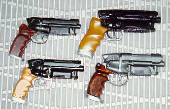
Our goal was to recreate this prop as completely and accurately as possible. There a have been countless tries, and most were off in so many ways. Never has there been a truly successful recreation of the form, function, and details of the venerable blaster until now. We set out to do it completely right. The underlying research was done by a team of two, Phil Steinschneider and yours truly, Richard Coyle with a late addition and many contributions by Craig Kovach. Armed with a screen capture print of the blaster from the scene where Deckard drops his gun onto the street outside Sebastians apartment, Phil visited several gun shops searching for the right gun. When he showed this scene shot to his gunsmith, Sandy Garret of Northern Virginia Gun Works, Inc., Mr. Garrett immediately spotted the details of a Charter Arms model Bulldog .44 special. 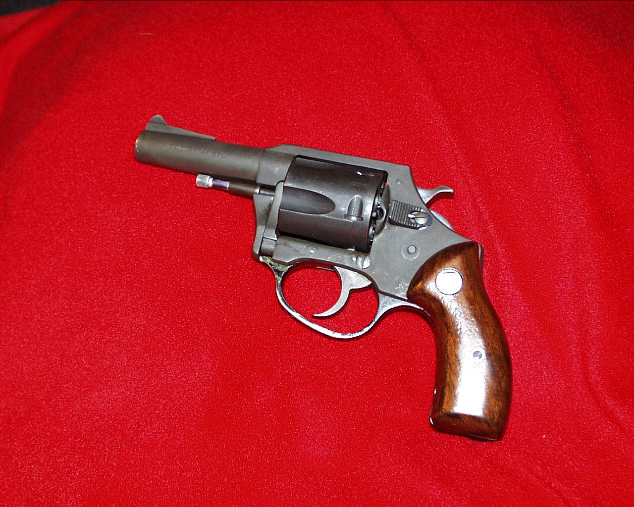
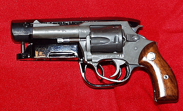
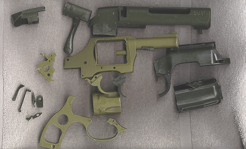
When Phil showed me pictures of a Bulldog I, too, knew we had finally found the correct hand gun: the triggers, the frame around the triggers, the removable trigger guard and hand grip frame, the cylinder swing out arm, the cylinder thumb latch, and the cartridge retainer and ramp for the cylinder latch pin all matched perfectly. Phil located and purchased a Charter Arms Bulldog .44 revolver and a Steyr-Mannlicher Model SL rifle that were used to pull molds and create master patterns for the project. The Steyr required barrel removal by an expert gunsmith, courtesy of Sandy Garrett at North Virginia Gun Works. 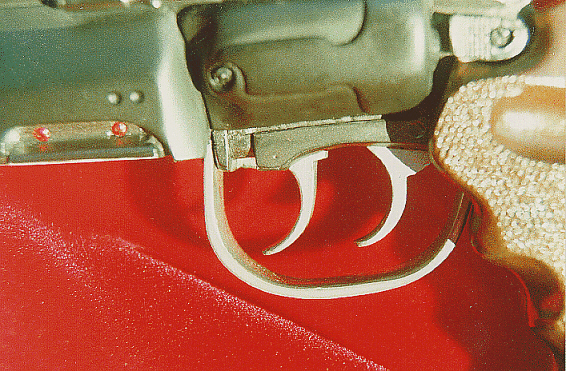
|
|

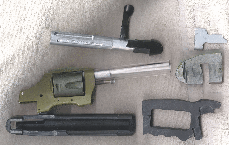
Project Blade RunnerI disassembled both weapons, laying aside the unneeded parts. Then, claying the openings that would cause problems with making the mold, I proceeded to clay line each incorporated gun component into mold boxes, and then cast RTV molds around these parts. Once the molds were cured, many sacrificial castings had to be made to use as working prototypes. I knew that quite a few would have to be cut up while working out all the fit and features we wanted.
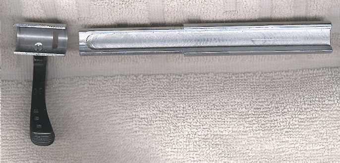
First I turned out a couple of test bolts using Delrin ® in order to get the right fit and work out details. Working with a softer plastic made for faster cutting and sanding. Then I began
machining a slot in the 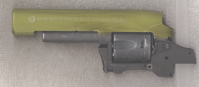 Once I lined up the Steyr receiver with the Bulldog over the stunt prop, I could see that, for the Bulldog barrel to line up with the centerline of the stunt prop barrel, the Bulldog would have to cut about halfway into the centerline of the Steyr receiver and bolt! At this point during the project, we had not yet located the original propmaker to confirm the functionality of the bolt. Either way, I believe it makes for a much more realistic model to have various working components, and the bolt action is one of the truly prominent features of this fabulous weapon.
|
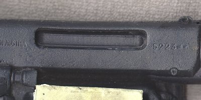 We know that the original Steyr bolt could not have been used in the
hero prop by the fact that what can be seen though the ejector port
of the gun and what shows up in the stunt castings has none of the features
of the real part. Neither the shell extractor arm nor the two
small holes in the Steyr part are present. Instead, the stunt
prop bolt has a long groove machined into it, which is not a feature
of the Steyr or any other bolt, but makes for nice decoration.
We know that the original Steyr bolt could not have been used in the
hero prop by the fact that what can be seen though the ejector port
of the gun and what shows up in the stunt castings has none of the features
of the real part. Neither the shell extractor arm nor the two
small holes in the Steyr part are present. Instead, the stunt
prop bolt has a long groove machined into it, which is not a feature
of the Steyr or any other bolt, but makes for nice decoration.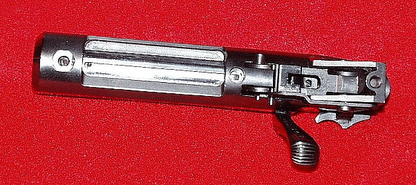
Project Blade RunnerPart of the difficulty in engineering a functional
bolt was nesting the Bulldog far enough into the Steyr receiver to achieve
the proper barrel alignment, while still retaining enough of the bolt
to allow attachment and rotation of the sleeve and cocking lever.
When placed in the proper position, the Bulldog occupies most of the
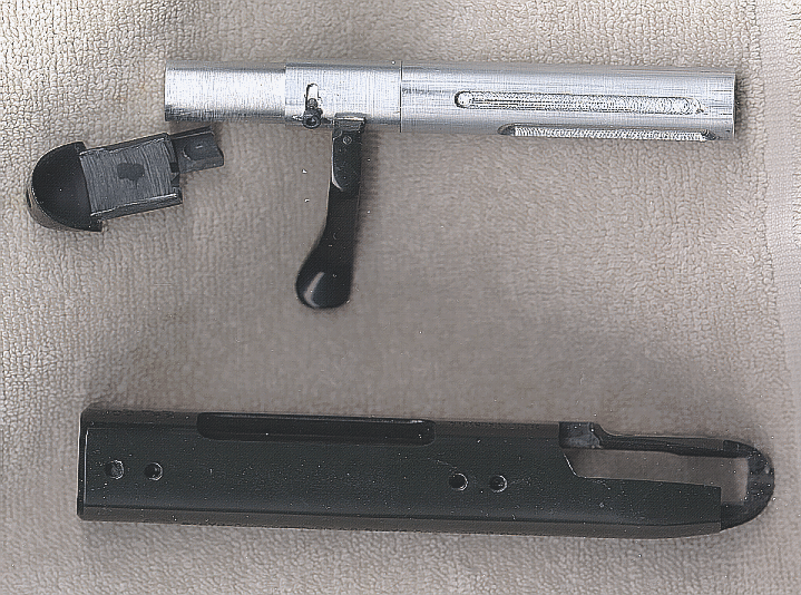
bolt cavity. Even after I cut and trimmed the bolt and attaching sleeve to the limit of their ability to grip each other, the Bulldog's frame was still too large to recess up into the receiver far enough. I found that the Bulldog's upper frame would have to be milled to fit properly with the functioning bolt. The real question was, what did the propmaker on the film do, or perhaps, if I were in his shoes, what would I have done? If the gun frame were to be modified heavily, would it still be safe? Ultimately, I concluded the following: The hero gun was to be a blank firing move prop. Once modified, the underlying revolver would never be asked to fire "live" rounds again. Blank rounds would reduce the compression load to the gun and its frame considerably. Thus, all I really would have needed to worry about was the gunâs ability to withstand blanks. So I concluded milling down the frame should be a safe change. Trimming the upper cylinder support of the frame should not weaken the revolver by much, if any, and any reduction in strength would be more than compensated for by the lessened shock of the blank rounds. So, I proceeded to mill the top of the frame down almost to the depth of the Bulldogâs rear sight groove. The sides were then milled to the width of the hammer slot at the rear of the frame. These modifications were necessary to retain sufficient the bolt material that a tube fitted to the turned down end would still have enough circumference to grip the rod under it. The cocking lever could then be fastened to this tube, which would in turn rotate around the rear of the bolt as the lever is raised. By capping the bolt just behind the lever and sleeve assembly using a casting of the Steyr bolt end cap (with attachment provided by a small 4/40 Allen screw), the bolt could be opened and pulled back with the same action as the original Steyr rifle. The stunt prop had a gun barrel that looked simply
like a heavy tube. There are no identifying marks nor any Unfortunately, even the Target model barrel is a little short, so the propmaker still would have had to take an aluminum tube or rod and machine it to fit over the rifled steel core. Either way, the sleeve used would provide the needed metal to drill and tap into for the Steyr receiver mounts and for the front ammo housing bolt that screwed into the underside of the barrel. As a bonus, these same screws could also help hold the outer sleeve onto the steel liner by extending through the aluminum and set contacting the steel. Of course, the 6/32 Allen screw serving as a front sight detail on the Steyr could also have served this purpose From study of the stunt props I determined that
the original prop barrel was 0.75-inch in diameter with a 500-thousandths
(.50 caliber) bore, so I used 3/4-inch acrylic tubing having 1/8-inch
wall thickness for the modelâs barrel. The 60-thousandths bore oversize
relative to the .44 caliber barrel of the Bulldog gives a bit
of extra clearance. Once all of the test fitting had been worked out,
I proceeded to fabricate the prototype bolt from aluminum and to retool
the best of the primary gun components. Each part was checked
and rechecked to insure all would fit together and work in concert,
while maintaining the highest level of detail and premium finish achievable.
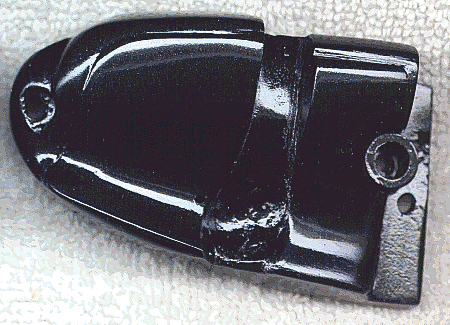
Molds and casts were made for each integrated Bulldog component: the triggers, hammer, cylinder, cylinder swing arm (also known as the crane), and a modified thumb latch from the Bulldog. Similarly, molds and casts were completed for the Steyr action, including the bare receiver, bolt end cap, ammo housing, .222 ammo clip (also known as the magazine), and the trigger guard. Note that the trigger guard and housing are one piece on the original Steyr, but they were separated into two components to create the hero prop gun. The master pattern for the left side cylinder cover
was made using aluminum tubing and Bondo ®. The right side was made
from three side cover castings cut and enlarged to fit, with a cylinder
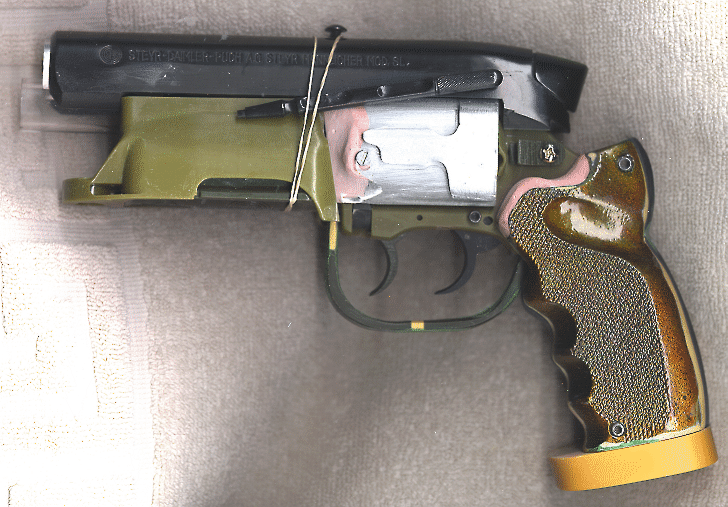
clearing carved out of the underside. I worked very carefully on these details, using the best stunt prop casting as a guide. Each master part was crafted to match the fit of its companion on the stunt prop paying particular attention to the placement of the side covers relative to details visible on the Bulldog frame. The side covers were adjusted to match every detail and fit on the master as compared with the solid cast stunt prop, such as the partial covering of the trigger pins. Every aspect was checked and rechecked to achieve a precise match. |
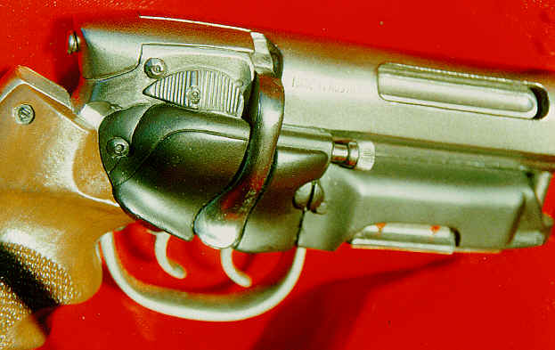
Project Blade Runner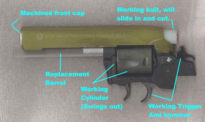 The main frame is, of course, the Bulldog with its trigger guard and pistol
grip subframe removed. To replace the grip frame I used an older
stunt casting to section out a frame that matched the outline of the blaster
grips. The master pattern grips were dissected from one of the best
stunt prop castings I had.
The main frame is, of course, the Bulldog with its trigger guard and pistol
grip subframe removed. To replace the grip frame I used an older
stunt casting to section out a frame that matched the outline of the blaster
grips. The master pattern grips were dissected from one of the best
stunt prop castings I had. 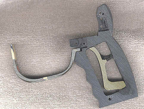
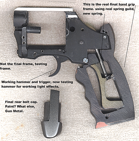
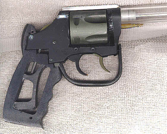
After cutting away most of the Bulldogâs subframe, I grafted the portion containing the hammer spring rest into the interior of the protoype's pattern grip frame. This gave me the perfectly proportioned mounting part for the new blasterâs hammer spring. Next came the trigger guard. This step required cannibalizing two guards from castings of the stunt props, which had to be enlarged in order to fit the real Bulldog frame. The guard had to be sectioned in the middle and additional material grafted onto the end. Noting that no screw is visible on the exterior
of the trigger guard on any stunt castings, and also that the rear of
the trigger seems to roll up into the frame by the grips, I engineered
a slot and groove mounting system. Observing that the front of
the trigger guard can pass directly over the cylinder swing arm screw,
I thought, âwhy not use it to do both?â So I did. And I
suspect thatâs exactly what the original propmaker did as well. Returning to the stunt prop, I compared the triggers and verified that the rear trigger was identical to the Bulldog, with its characteristic grooves and profile, so this is in fact what was used on the hero prop. Interestingly, the front one was exactly the same -- just cut down slightly to fit into the Bulldog's frame where the front part of the subframe used to mount. Concluding (with the mindset of the propmaker) that I would probably want to avoid drilling into a chromoly steel gun frame, I quickly found I could use the front subframe pin as the new trigger bushing mount. Next came the new custom pistol grip frame. Once again figuring that I would not want to drill into the steel frame, I milled the new grip frame to fit into the Bulldog's frame in the same way the Bulldog's subframe previously mounted in the rear. At this point it was time to begin fitting the Steyr
receiver onto the Bulldog frame. From the stunt prop it was obvious
that two 4/40 Allen screws were used to hold the front of the Steyr
receiver to the firing barrel. However, With the center cut away, there was no easy way
to mount the Steyr receiver onto the Bulldog , and it is not readily
apparent how the propmaker originally secured the rear of the receiver
to the revolver frame, either. The only visible rearward screw
is the one just above and to the rear of the safety, but on the stunt
castings this screw is too high and could only have screwed into the
rear bolt cap. In fact, I believe this is exactly what that screw
was used for â to hold the rear bolt cap (and thus the bolt) in place.
The only option was to engineer a new rear mount for the Steyr. After careful consideration, I settled on a slot and rail design for the mount. I cut two slots into the inside walls of the Steyr receiver (one on each side) and then glued two corresponding rectangular rails onto the Bulldog frame. This may well have been done by the original propmaker, by either pinning or soldering two like metal bars onto the steel revolver frame of the hero prop. This design made the Steyr receiver very secure as well as easy to remove. |
Project Blade Runner
Next I turned down an aluminum cap to plug the moon-shaped
cavity in the end of the Steyr receiver where the original rifle barrel
threaded in, again copying the necessary details from the stunt prop.
I made this component a two-part assembly, with the small center
bead as a drop-in part.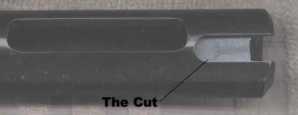
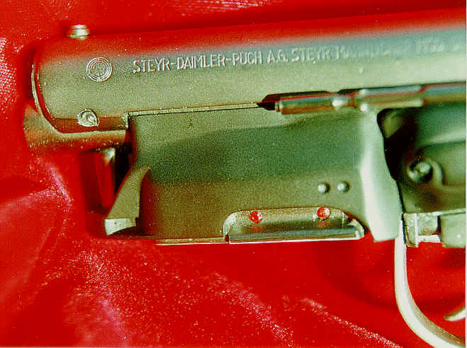
The final critical detail on the receiver was to
recreate the actual Steyr serial number from the original hero prop.
Our new casting obviously had a different serial number, so I milled
a slot into the "hero" receiver and then carefully sanded
and fitted a drop-in serial number plug from my best copy of the stunt
prop. 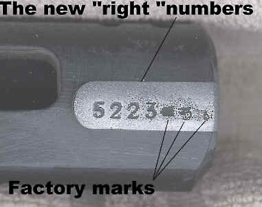
Now that the Steyr receiver had been successfully mounted and the pistol frame details worked out, it was possible to finish fitting the side covers to the prototype. With the swing arm installed and the cylinder set in the proper position in the Bulldog's frame, I proceeded to fabricate a cylinder rod out of several pieces of brass tubing by soldering them together.
The two side covers had to fit over the cylinder and allow it to turn while also matching the proper placement and shape of these parts relative to the stunt prop. It took many days to shape and carve these parts out.
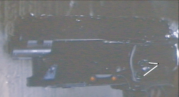 From study of film scenes and the stunt prop, we could see two holes
positioned in a vertical line at the front edge of the left side cover.
(Note that the stunt copies seem to have had the bottom one clayed
over.) When the cover is properly aligned over the frame, these
two holes were found to line up right over the cylinder swing arm.
Thus, the left cover could be mounted to the swing arm and could then
swing open with the cylinder. This arrangement was no accident,
as it allowed easy reloading of the hero prop on the set. We
wanted to recreate all the functional details of the original, so the
same design was incorporated into the model.
From study of film scenes and the stunt prop, we could see two holes
positioned in a vertical line at the front edge of the left side cover.
(Note that the stunt copies seem to have had the bottom one clayed
over.) When the cover is properly aligned over the frame, these
two holes were found to line up right over the cylinder swing arm.
Thus, the left cover could be mounted to the swing arm and could then
swing open with the cylinder. This arrangement was no accident,
as it allowed easy reloading of the hero prop on the set. We
wanted to recreate all the functional details of the original, so the
same design was incorporated into the model.
As I worked with the cylinder in the revolver, it
became apparent that a spring was needed to hold the cylinder latch
rod in place. This necessitated the addition of yet another ring
of cut tubing, which was soldered into place to hold the locking spring.
All in all five sections of tubing had to be spliced together
to make this one rod. 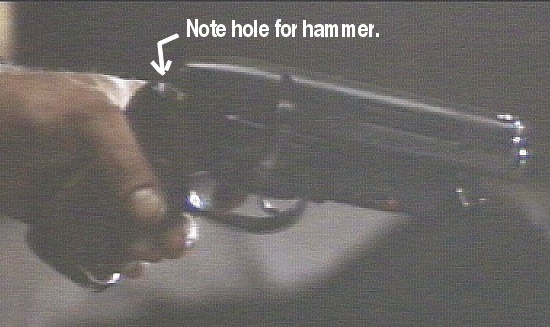
Next came the working trigger and hammer.
From the stunt prop it was evident that the Steyr receiver had been
cut to fit around the revolver frame, including removal of a section
at the rear to allow the hammer to drop through. But it was also
evident that the Steyr's rear bolt cap was uncut, so the only solution
to fitting all the components was to "bob" the hammer.
Charter Arms did offer a factory bobbed hammer as an option, but the
factory piece is still too large. Either way, the propmaker had
to cut down the Bulldogâs hammer to spare the 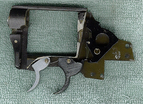 bolt cap and have everything work properly. Following suit,
I bobbed the recast hammer to clear the end cap.
bolt cap and have everything work properly. Following suit,
I bobbed the recast hammer to clear the end cap. 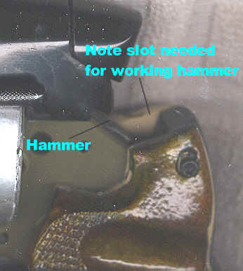
Using a cut away pistol frame, I studied the working of the trigger and hammer actions carefully to recreate them in the model. I found that the Bulldog hammer has a small spring loaded lever that the trigger pushes on to the throw the hammer back, and that for the trigger to return to the fire-ready position, it had to stroke by this lever to get below it again. This lever had to be able to allow the trigger to pass, and then it had to spring back in place so that the trigger could engage it again. Prototype testing demonstrated that the cast polyurethane was not strong enough to withstand this pressure when cast to the same dimensions as the steel part, so I was forced to both thicken this lever as much as possible and to recast it out of epoxy.
Project Blade Runner
Each hammer required a small hand-drilled hole to allow placement of a tiny spring in it, as well as a hole for the brass rod that provides the pivot for the actuating lever to swing on.
I then worked on the hammer return spring assembly.
The stock Bulldog hammer spring runs on a special ball ended
rod that traps the spring between the ball end (just below the hammer)
and a rectangular washer that is loaded against the grip sub-frame at
the lower end. These rods are no longer available from the 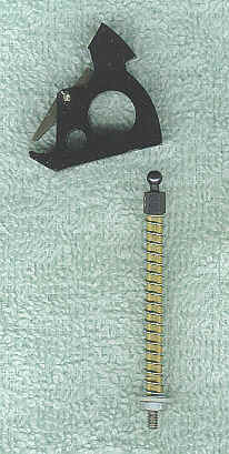 manufacturer, so a reproduction was required.
From a trip to the local hobby store, I managed to find a suitable small ball and socket rod end assembly. This particular part is used in RC planes and is made to screw onto 4/40 threaded rod. I cut some threaded rod to the appropriate length and then sheathed the threads with a section of brass tubing to eliminate spring hang-up on the thread peaks. I finished off the assembly using a nylon washer that fit over the brass tubing and a 4/40 nut to fasten it all together. The end result works flawlessly.
The trigger also needed major modifications to
be functional as a polyurethane casting. The original steel trigger
on the Bulldog has very thin sides with a deep slot right through the
middle where a scissor-shaped return spring resides. These thin
walls would never work cast in plastic, so I filled the recess and designed
the new trigger to use a straight coil spring. This effort required
four reorders from a spring company to get a workably sized spring.
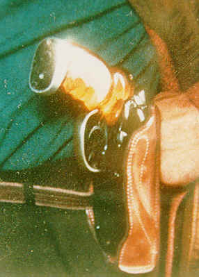
From a study of many film shots, the pistol grips seem to have been a translucent amber material. Working with fiberglass resin and various dyes, I experimented until I had just the right color.
After sanding and smoothing the grips, the undersides were painted silver to mask the grip frame internals, followed by painting with a coat of Krylon® Crystal Clear enamel.
The specialized side rod pointer component on the blaster needed a mounting system, so I cut a slot into it and then glued a strip of plastic into the slot. The side rod could now be glued directly to the left side cover to match the prop gun.
The rear section of the side rod was removed and glued into a mold box to allow separate casting and maximum retention of its knurling details.
Included in this mold box was the cylinder thumb release latch, the Steyr safety latch, and the little knob from the front of the right side cylinder cover plate.
As it seems that the rather large but shallow slot-head
binding screw used on the right side cover is apparently no longer available
(or at least is uncommon), I cut down a readily available binding head
screw, which is similar but  with a slightly taller profile, for use as a pattern to mold.
For the ammo housing, careful placement and drilling of the two small holes on the left side was required in order to match the original prop. As suspected, we later confirmed through our interviews with the original prop designer that these access holes were added to reach the on/off switch for the LEDs. This ammo housing was then cut and fitted so that one side overlapped the right side cylinder cover the same way the original prop did, as evident in the stunt copies.
Like the receiver on top, the ammo housing also ended up with a deep round milled cut to fit under the new revolver barrel. I also incorporated a slot and bar locking system for the housing and its ammo clip. In order to fit, the clip had to be cut down and trimmed to include the LEDs, battery holder, and electrical switch within the housing.
Interestingly, the original Steyr bolt lever is straight, unlike the lever observable on the stunt prop, which is curved to match the contour of the right side cover. The Steyr cocking lever had to be heated and bent inward to match the this contour. Presumably, the original propmaker had to do the same.
The Steyr bolt rear cap was trimmed and then filled in to fit onto the rear of the bolt.
With the working parts of the prototype completed, we were now ready to cast all of the converted and modified components to make the final model.
Thus, working molds were made using these newly created master parts.