Building a Saber for the Dark Side
By David Meyer
 Building
a Saber for the Dark Side
Building
a Saber for the Dark Side
by David Meyer
If you've ever been in a Sharper Image, you've probably seen the slick prop reproductions of Luke Skywalker's and Darth Vader's lightsabers put out by ICONS. And, if you are like me, you probably didn't want to shell out $300 or more for them. When I found out that many Star Wars props were built using found objects, I had to try to find the parts and make my own.
When Star Wars first hit the theaters in the summer of 1977, one of the things that stunned the audience was the incredible special effects -- effects like no one had ever seen at that time. What made this even more amazing was the low budget that George Lucas was given to film his blockbuster. Given the budget he had, he didn't have the luxury of having props machined from scratch. Indeed, his clever staff was able to find commonplace items and turn them into convincing weapons and tools from a galaxy far, far way.
This article focuses on one such weapon - Darth Vader's lightsaber. It is intended to be a "how-to" piece, describing the steps to creating a convincing replica of the preferred weapon of Lord Vader. Throughout the article, I list places where you can find some of the pieces necessary to complete this project. Note that I have no affiliation of the places I mention in this article. I note them for your convenience.
You may have seen "officially licensed" prop replica lightsabers in The Sharper Image or other stores. While those sabers are very nice reproductions, they are machined rather than built from found objects. Completing this project will yield a more "authentic", and thus more satisfying, replica than the machined reproductions put out by ICONS.
Background on the Lightsaber
In the first Star Wars movie, Darth Vader's lightsaber had at least 3 variations. There were props that hung from the belt of Darth Vader as well as props used for the combat scene with Ben Kenobi.
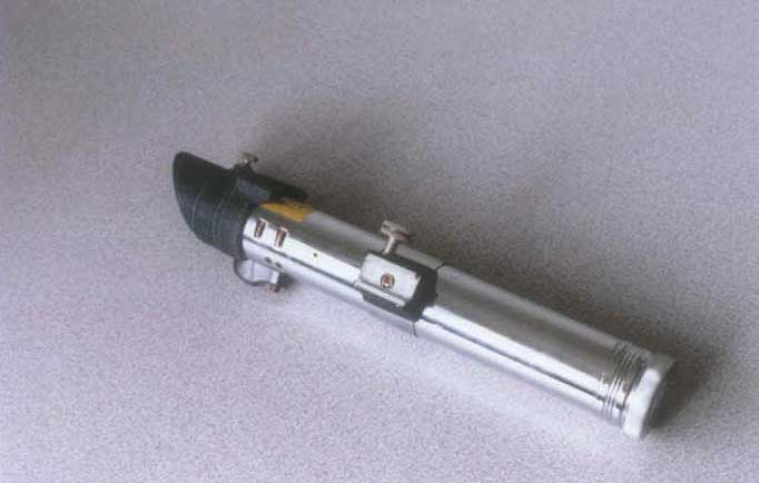
The 2 variations seen hanging from Lord Vader's belt were based upon Heiland Synchronar and Heiland 3-cell flash tubes. These flashes were used in 1940's press cameras. If you look in movies with press photographers of that period, you will likely see a Heiland or a Graflex flash clamped to one or both sides of their cameras.
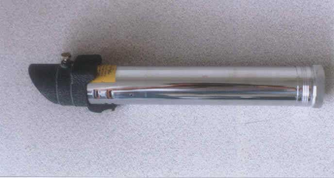 (fig. 1 - Heiland 3-cell flash)
Both flashes hold 3 D-cells and look almost exactly alike. The main difference is that the rectangular slots on the side of the Synchronar have rounded corners and the slots on the Heiland 3-cell have sharp corners. Another difference is in the head of the flash. In the 3-cell, there is a spring that juts out, whereas the Synchronar has a black spring-loaded plastic piece with a small hex nut holding it in place.
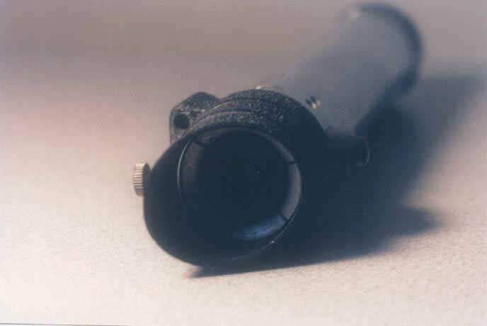
(Head of Heiland 3-cell flash. Note the spring in the head of the flash.)
One other variation is the screw-on end cap. One flash has an octagonal end cap while the other one has a knurled end cap. Since I've seen Heiland flashes (Synchronars and 3-cells) with both styles of end caps, I don't consider one more "authentic" than the other. Either flash can be used to build a Darth Vader lightsaber and still be considered authentic. If you've seen the ICONS replica, you'll see that they use the Synchronar-style head and the knurled end cap. If you've seen the pictures in The Star Wars Chronicles, you'll see pictures of a Synchronar with the knurled end cap as well.
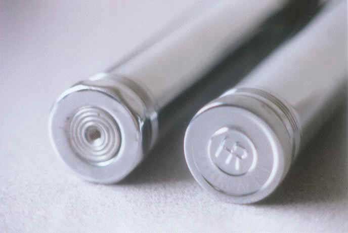 (
fig. 3 - Two variations of the end caps from Heiland flashes: octagonal, left,
and knurled, right.)
(
fig. 3 - Two variations of the end caps from Heiland flashes: octagonal, left,
and knurled, right.)
Saber For the Dark Side
The 3rd variation was used for the melee combat scene with Ben Kenobi. For combat scenes, a rod wrapped in reflective tape was attached to the lightsaber hilts. The problem with the Heiland flash was that they couldn't reliably get the rod stuck in the flash tube. They decided to modify a Graflex 3-cell flash (also used as the basis of Luke Skywalker's lightsaber) instead. For this article, I chose to use a Heiland 3-cell flash as the basis for the saber because the Graflex version would have required considerable machining.
Materials
You will need the following materials to complete this project:
- Heiland 3-cell or Synchronar flash with black reflector shroud
This is the main component of the lightsaber. It can be found at camera shows and some photo dealers. This used to be a fairly common item, but lately they've become more difficult to find. You can find dealers that deal in large-format equipment in Shutterbug magazine. If you're patient, a Heiland can be had for $35, but if you're not, be prepared to pay $75-$150 for it. Unfortunately, most dealers know that Heiland (and Graflex) flashes were used to make lightsabers, so be prepared for a long wait if you decide to hold out for a bargain. When you buy a flash, be sure the flash comes with the black shroud (which is used to connect the reflector to the flash). There were two variations of the shroud. The one you want is approximately 2-3/4" long from the tip of the head to the base. The one you don't want is about 1-1/2" long. Also, if you want to use the stock Heiland clamp, you'll want to be sure the flash comes with the clamp as well.
(
fig. 4 - Heiland 3-cell flash with stock center clamp)
- Heiland flash clamp
-or-
- materials to scratchbuild your own clamp
The clamp was used to affix the flash to the side of a press camera. In this case, it will be used to hold the calculator "bubble" display or circuit board and is affixed to the center of the flash. I've seen replicas built using the stock Heiland clamp, but this clamp is about 3/4" shorter than what was used in the movies. The problem is that if you decide to use the calculator bubble piece, you'll find that only 3 or so bubbles fit into the clamp, which doesn't look right. I've chosen to scratchbuild my own clamp. If you have access to a drill press and some basic tools, this shouldn't be too difficult. If you don't, you can either use the Heiland flash clamp, or buy a machined clamp that others have made. Be prepared to pay $40 for a machined clamp if you can't build your own. You can buy one from EDC Studios at http://members.aol.com/edcarmory.
- black vinyl cloth
This is wrapped around the flash clamp (whether custom made or stock). The clamp part is left exposed, with only the band that wraps around the flash being covered.
- calculator display bubble a 1970s LED calculator
-or-
- connector edge from a computer card that fits into a 44-connector bus.
The display piece out of a 70s LED calculator was used in the first Star Wars movie. It is simply a 1/2"x 2" piece of plastic with 8-11 bubbles on them. These magnified the numbers of the older LED calculators so they could be read. This piece was used as the "activator switch" and was slid into the clamp that was affixed to the center of the flash. You can often find LED calculators at resale shops and flea markets. Unfortunately, will need to destroy the calculator to get the plastic bubble piece out. If you can, find a cheap Texas Instruments model, as these bubbles are easier to work with than some others. Stay away from HP calculators. The bubble display has raised edges on the top and back of the display piece making it too thick to slide into the clamp without heavy modification. You should be able to get an appropriate calculator for around $5-10.
- 1 or 2 tubes of plumber's epoxy putty for the 6 hand grips
The original lightsabers (both Luke's and Darth Vader's) used windshield wipers from a British vehicle for the 6 handle grips affixed around the bottom of the flash. In "The Empire Strikes Back" and "Return of the Jedi", the windshield wipers were replaced with cast grips. The correct windshield wipers are difficult, if not impossible to come by, so I chose to use plumber's epoxy putty to cast my own grips. In the first movie, the windshield wipers tended to fall off of the flash because the handle is rounded, but the backs of the wipers were flat. For the later movies, the wipers were replaced by grips cast in resin. The backs of the grips were rounded so they would stick to the flash handle more securely. The kind of putty you need to use comes in clear plastic tubes with caps on both ends. The putty comes in a roll, with two colors. The center is one color and the outside is a different color. You mash the putty until the putty turns one uniform color. This stuff starts to cure in 5 minutes and is rock hard within 15-20 minutes. Oatey's is a popular brand, but there are several others that will work just as well. The putty will cost you about $8 for enough to do 6 grips. You can find plumbers putty at most hardware stores and home improvement centers such as HQ, Home Depot, or Builder's Square.
If you really must have rubber grips, EDC Studios makes a set of extruded rubber grips that can be used for handle grips. These will cost you about $20 for a set of 6.
- a roll of double-sided tape
This is used to affix the vinyl cloth to the flash clamp and to affix the handle grips to the flash. 3M VHB (very high bond) is the best tape to use, but it costs $50 a roll and can only be purchased through industrial catalogs. The standard double-sided tape found at the local hardware store will work as long as you've shaped the back of the handle grips to fit the flash. The tape will cost you about $2-3, which will be enough for plenty of grips.
- 2 sheets of basswood (3/16" thick and 3/32" thick) for mold
If you choose to make your own grips, you will need to build a mold from basswood. This can be found at most hobby and craft stores in a large display box which contains assorted thicknesses of wood. Be sure you get basswood and not balsa. Balsa will work, but the mold will not hold up to more than 3 castings. If you mess up a casting and need to do more, your mold will be done before you are. Basswood will hold up for several castings as long as you wax the mold. In addition to basswood, you will need a solid, smooth piece of plywood. I found a 12" circular piece at the hardware store for about $7. The basswood cost me about $4.
- D-ring used for hanging pictures for hanging the saber from your belt
The D-ring you need can be found at a hardware store. You need one designed to be bolted to a picture frame. They usually come in packs of 2-4 and shouldn't cost more than $2.
If you decide to scratchbuild a flash clamp, you'll need:
- 1/4" zinc-plated steel bar
You will find this in the industrial section of your local hardware store. Often, there will be a display of several lengths and thicknesses of metal bars, rods, and u-channels. The one I used is 1 foot in length. You will need to cut two 2" lengths from it with a hacksaw. One of the lengths will have a 8/32" hole drilled through the center of it. The other will be tapped with a 6/32" tap so that it can accept a machine screw. The bar will cost about $1.50. If you don't want to hacksaw it yourself, you might be able to con the person at the hardware store to do it for you.
- package of thin K&S aluminum sheet (.02 or thinner)
Hobby shops and some hardware stores stock K&S aluminum sheet. Look for a display stand with lots of small metal rods, squares, and sheets. Make sure you get sheet that is thin enough to bend easily by hand. It will be cut using metal snips and then bent in several places, gradually acquiring the shape of a Graflex-style clamp. Be sure you don't get a sheet that is too thick. If it's too thick, you will have a terrible time bending it unless you have tools specifically designed for folding metal. This will cost about $3-4, which will give you enough to make about 4 clamps, should you need them.
- 6/32" x 1/2" phillips machine screw
This will be used to affix the clamp to the flash. You can get them in packages of 5-10 for about $1.
- 1 foot length of PVC pipe, about 1/4" around
This will be used to round the back of the cast grips so that they conform to the shape of the flash.
- 400 grip wet/dry sand paper and flat black paint
Building the lightsaber
Now that you've acquired the materials you need to build the lightsaber, we'll get started.
Preparing the Flash
First we'll prepare the flash tube. Assuming your flash came with the reflector, you'll need to remove it from the black shroud. The reflector is attached by two rods held in place by thumb screws. Remove the screws and the reflector will slide out of the shroud. Set it aside...you never know if you ever want to use the lightsaber as a flash again. None of the modifications, by the way, disable the flash. It can easily be used as a flash again should the mood strike you.
Take the center clamp off if your flash came with one. It is held in place with a single Phillips screw. It's easiest to take off the end cap and slide it off the bottom. Some flashes come with multiple brackets. You will want to remove them and stick with the single black clamp that comes with the flash. They are usually affixed with one small screw each.
Unless you managed to get a pristine flash, you'll probably have to clean up the flash a bit. Many of these tubes have stickers and foil tape on them. You'll want to remove the tape and clean up the sticky spots using metal polish.
If your shroud is flaking paint, you may want to give it a coat of flat black paint. If it's in pretty good shape, you can leave it as it is. A little chip here and there give it a nice weathered look anyway.
You will notice that there are 3 sets of slots towards the top of the flash. These are where the synch cords are plugged in. They may be labeled, or even covered, with stickers...again, remove these before you start working on the flash. Also note that the slots may be tan or brown instead of black. If you want, you can remove the inside guts of the flash and paint it black, which is the cleanest way to do it. To remove the guts, you should first take off the shroud, which is held in place by the top thumb screw. Then you need to take out the screw at the top of the flash on the plastic piece with the red button. The plastic piece with the button will lift off and the inside piece will slide out of the tube. You may need to unscrew the bottom cap and push the inside piece through the top with a long screwdriver. This piece can be painted and put back in and reaffixed to the flash again. If you plan on using this flash again for it's original purpose, I'd recommend against doing this.
Making the Belt Ring
Next, you need to take the D-ring assembly and use a flathead screwdriver to bend open the strip of metal that holds the D-ring in place. Take a pair of metal snips and cut off one side of the metal strip up to where it encircles the D-ring. Bend it back again so that the D-ring is encircled again by the partial metal strip. Now, use the snips again to trim the other strip down to about 3/4" in length (see the illustration below). Now, put the shroud back on and put the screw through the hole in the D-ring assembly so that the D-ring points towards the top of the flash. Screw the shroud back down on the flash.
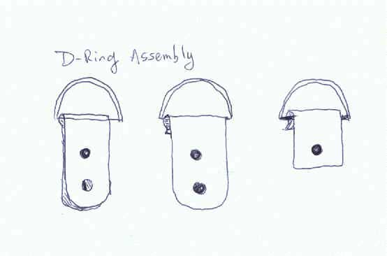 (
fig. 5 - Preparing the d-ring for use with the flash)
(
fig. 5 - Preparing the d-ring for use with the flash)
Making the clamp
Next, if you plan on using the Heiland clamp that came with your flash as the center activator switch, you should put it back on the flash (assuming you took it off when you cleaned up the flash). Make sure that the clamp is about at the center of the flash.
If you don't want to use the stock clamp, you can build your own. If you don't have access to a drill press and a good bench vise, you will probably not want to try this. If you don't like the Heiland clamp, you can either try scavenging a Graflex clamp (good luck) or buy a fabricated clamp from EDC Studios. If, after all that, you decided to stick it out with me, read on.
 (clamp1.gif
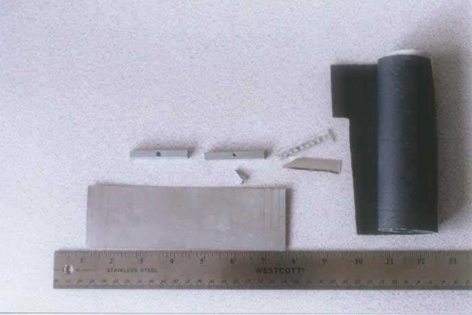
- caption: fig. 6 - Materials needed for building your clamp)
(clamp1.gif
- caption: fig. 6 - Materials needed for building your clamp)
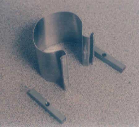
To make the band of the clamp, you'll need to bend the aluminum strip so that it resembles a Graflex clamp. First, take the sheet of aluminum out and measure off a 2" wide x 6-5/8" long strip. Use a good pair of metal snips to cut the strip to size. Next, you will mark 4 lines across the end of the strip using the measurements illustrated below. The one closest to the end of the strip is 1/8". The next one is also 1/8". The last two measurements are 1/4". Do this for both ends. These lines mark where you will be bending the aluminum. Each bend will be 90 degrees. When you've done each side, bend the aluminum strip around your flash and make it so that the final 1/4" bends on each side of the strip mate. See the following illustrations for how the aluminum strip will look once all of the bends have been done.
Saber for the Dark Side
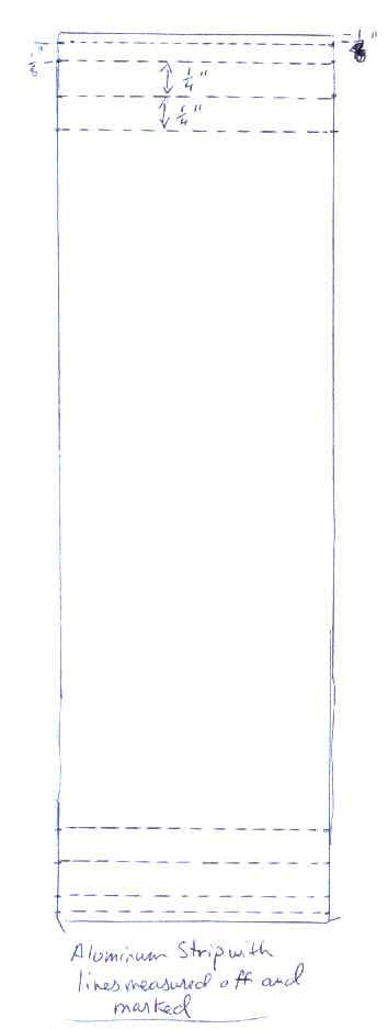 (
fig. 7 - Measurements on the aluminum sheet that will be shaped into the clamp)
(
fig. 7 - Measurements on the aluminum sheet that will be shaped into the clamp)
( fig. 8 - Aluminum strip bent to the correct shape)
Once you've bent the aluminum in the appropriate shape, you need to create the two 2" steel rods that will slide within the two 1/4" areas of the clamp. These rods will be drilled and tapped so that a screw will fit through one end and fasten down the other end so that the clamp is tight. Measure off a 2" length of the 1/4" steel rod and cut the rod with a hacksaw. Putting the rod in a bench vise will make this much easier. Then measure off another 2" length and cut it off.
Now, use a punch to drive a dent into the center of both of the rods. This will keep the drill bit from walking as you drill through a hole through the center of the rods. Take one rod and clamp it down to the drill press and use a 8/32" bit to drill a hole through it. Take the second rod, clamp it down, and drill it through with a 7/64" bit. This is the rod you're going to tap (thread) with a 6/32" tap (see illustration). Now, use a 6/32" tap to thread the second rod. If you've never used a tap before, you need to be patient and don't try to go through the entire rod right away. You'll need to turn the tap a quarter turn, back it off, turn it another quarter turn, back it off, and so on, until you get through. I know from experience, having broken off a tap in steel before.
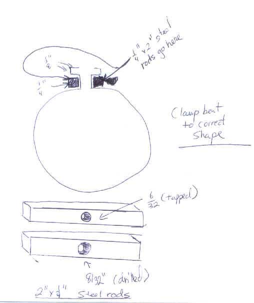 (
Fig. 9 - Clamp bent to the correct shape and steel rods to be used with the
clamp)
(
Fig. 9 - Clamp bent to the correct shape and steel rods to be used with the
clamp)
Once you have the hole drilled in one rod and the other rod tapped, you need to drill 8/32" holes in the part of the clamp that mates together. The hole should be centered in the clamp and should match up with the two rods you've drilled holes in. This is where the screw will go.
Once you've done this, you need to take a 6/32" x1/2" machine screw
and put it through the 8/32" hole in the first rod. Then push it through
the two holes in the clamp and line it up with the second rod on the other side
of the clamp. This screw should screw right into the hole you tapped. Screw
it down until it's snug. Now, loosen it up and take out the screw so you can
put it around the flash.
(clamp3.gif - caption: Fig. 10 - Partially assembled clamp)
Cut a piece of the black vinyl cloth so that it can cover the band of the clamp. You want to leave the jaws of the clamp exposed. Use double-sided tape to affix the vinyl to the band of the clamp. Now, put the clamp on the flash, making sure it's centered on the flash. Then put the two rods back in place, put the screw back in, and tighten it down.
Saber for the Dark Side
Dismantle the calculator and pull out the bubble display. This may take a little
work, prying it off carefully with a small flathead screwdriver. You may need
to use an X-acto knife to clean the tiny connecting rods on the back of the
bubble off so the bubble will slide easily into the clamp. Now loosen the clamp
enough to slide the bubble into the jaws and then tighten down the clamp again.
The tension of the clamp should keep the bubble in place.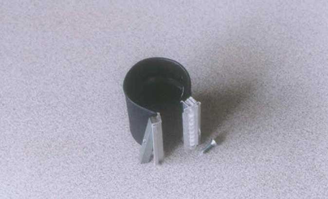
( Fig. 11 - Assembled clamp with calculator bubble and vinyl cloth)
Making the handle grips
Now let's concentrate on making the handle grips. If you decided to take the easy way out and buy handle rubber grips from someone that makes them, you can skip this section. The handle grips, if you are looking at them from the end, look like an upside-down T. The grips measure 3" long by 1/2" wide by 9/32" tall.
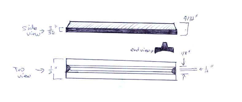 (
Fig. 12 - Side and end view of grip with measurements)
(
Fig. 12 - Side and end view of grip with measurements)
In order to make the handle grips, we will first need to fabricate a simple
one-part mold. We will use the smooth plywood as a base and glue the basswood
pieces (cut to the right size) to the base to form the mold. Here is a schematic
of the mold you need to build.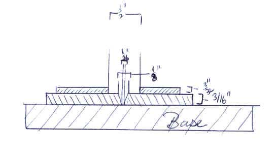
( Fig. 13 - Mold schematic for handle grips)
Use the template above as a guide to gluing the basswood to the plywood base. Be sure that you make basswood strips at least 4" long to accommodate a 3" grip. The extra inch gives you a little margin for error.
Cut the 3/16" basswood sheet into two pieces that are 4" long. It doesn't really matter how wide you cut them. To get the angle on the edge you will need to lightly sand the edge. Using wood glue, affix the 3/16" sheets onto the base, making sure they are placed correctly (1/16" apart from each other). This will result in a 4" long V-shaped channel.
Next you need to cut the 3/32" basswood into two more pieces, also 4" long. Make sure they aren't wider than your 3/16" sheets that have already been glued to the base. Glue the 3/32" sheets onto the 3/16" basswood sheets, making sure the placement is correct. Let the mold dry for an hour before you try to cast your grips.
Once the mold is dry, you need to wax and buff it using car paste wax. You should put at least 3 coats of wax on the mold. You might try using a Q-tip to get into the crevices. You don't want the putty to stick to the mold since this will not only ruin the grip, but your mold as well.
Once the mold has been sufficiently waxed, you need to spray the 1/4" PVC pipe with Pam or some other non-stick spray. This makes an excellent mold release. Set the pipe aside.
Saber for the Dark Side
Now prepare the putty. Once you start kneading the putty, you only have about 5 minutes of working time with it, so work quickly. When you take the putty out of the tube, it will likely be sealed in a plastic wrapper. Remove it from the wrapper and start kneading it. I wear latex gloves while doing this. I'm not terribly fond of the cleanup involved when working with any type of A/B epoxies, so I like to protect my hands as much as possible. Keep kneading the putty until it is a uniform color. Then press the putty into the mold you've just completed. Make sure the putty gets completely into the channel. Now, take the PVC pipe and press it firmly into the top of the mold. This will shape the back of the grip so that it will match up with the flash tube. You might have to roll the PVC pipe back and forth a little to get an even camber. If any putty is forced out of the mold, just trim it with an X-acto knife later. Let the putty cure for 15 minutes. You will notice the putty heating up as you work with it. This is normal...it is a sign that the putty is starting to cure.
Carefully pry out the grip with a tiny flathead screwdriver tip. It will become apparent why I suggested 4" rather than 3" for the length of the mold. Prying out the grip will likely damage the top of the grip. This should be no problem since we have 1" spare that we can cut off.
The putty will be mostly cured but is still flexible enough to cut easily with an X-acto knife. Cut the excess length of the grip off at both ends so that the grip measures 3" long. Make sure the cut is at 90 degrees. Now cut the top part of the grip (the part that is shaped like a V) at an angle as shown in Figure 12. You can eyeball the angle. Only the top part of the grip should be angled this way. The base of the grip should remain at 90 degrees. Do this at both ends. Also trim any excess putty from the sides of the grip.
Now, repeat the steps for casting the grips 5 more times. It generally takes me about 2 hours to get a set of 6 grips. If you want to get really fancy, you can create a mold like the one above, but make it so that it can accommodate 2 grips at a time. This will speed up the process significantly. Do not, however, try to make a really long channel and hope to get all 6 grips out of one length of putty! You will be sorely disappointed.
Once you have all 6 grips, test fit them to the flash. Make sure that they fit reasonably well to the camber of the flash. If any of them don't fit quite right, you can use a half-round file to improve the profile of the grip. You shouldn't have to do this if you used the PVC pipe correctly.
Let the grips fully cure for an hour. Then wet sand them with fine-grit sandpaper (400 or above) to smooth them out a bit. Then you can shoot them with a coat of black paint and set them aside.
Finishing off the Saber
Now that the clamp is in place, you can put the handle grips on the flash.
Cut strips of the double-sided tape so that they fit on the back of the handle
grips. You might want to cut two for each grip and stick them one on top of
the other. This will build up the surface area underneath the grip so that it
adheres to the flash a little better. Stick the grip onto the flash so that
the end of the grip just touches the projection at the bottom of the end cap.
That is, part of the end cap will be covered by the grip. There should be about
5/8" between the top of the grip and the clamp. Do this for the other 5
grips, making sure they are spaced evenly apart.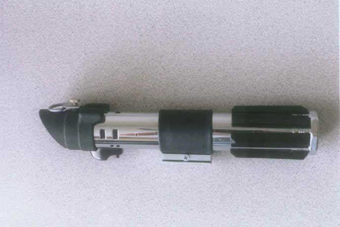
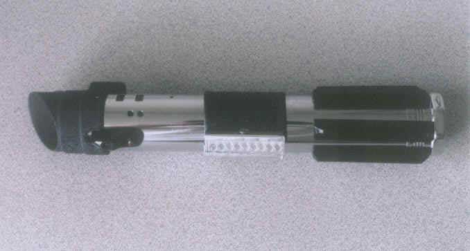 (
Figs. 14 and 15 - The completed lightsabers)
(
Figs. 14 and 15 - The completed lightsabers)
And that's it. You have a nice replica of Darth Vader's lightsaber for much less than the cost of an ICONS replica. Now if it only worked!