Blade Runner Blaster: Take Two
By Richard A. Coyle
Blade Runner Blaster: Take Two
By Richard A. Coyle
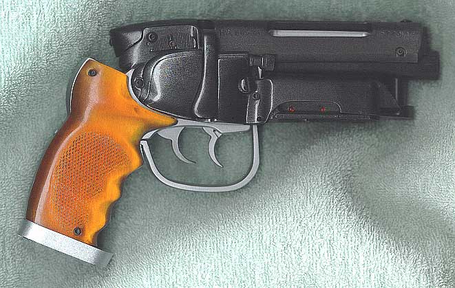 Not
long after I completed the first run of working Blasters and penned the Making
of saga, Craig Kovach was writing and talking with me about the really
finer and nitpicking details of both my model and the real Blade Runner Blaster.
Craig had been doing some of his own homework, and after a tip from Phil Steinschneider,
he visited a nearby Planet Hollywood that had one of the stunt props in a display
case. He took as many pictures as possible to share and, aided with a very poor
sixth generation casting of one of the stunt castings and his own well-worn
copy of Blade Runner The Directors Cut on DVD, kept grilling me relentlessly
on details.
Not
long after I completed the first run of working Blasters and penned the Making
of saga, Craig Kovach was writing and talking with me about the really
finer and nitpicking details of both my model and the real Blade Runner Blaster.
Craig had been doing some of his own homework, and after a tip from Phil Steinschneider,
he visited a nearby Planet Hollywood that had one of the stunt props in a display
case. He took as many pictures as possible to share and, aided with a very poor
sixth generation casting of one of the stunt castings and his own well-worn
copy of Blade Runner The Directors Cut on DVD, kept grilling me relentlessly
on details.
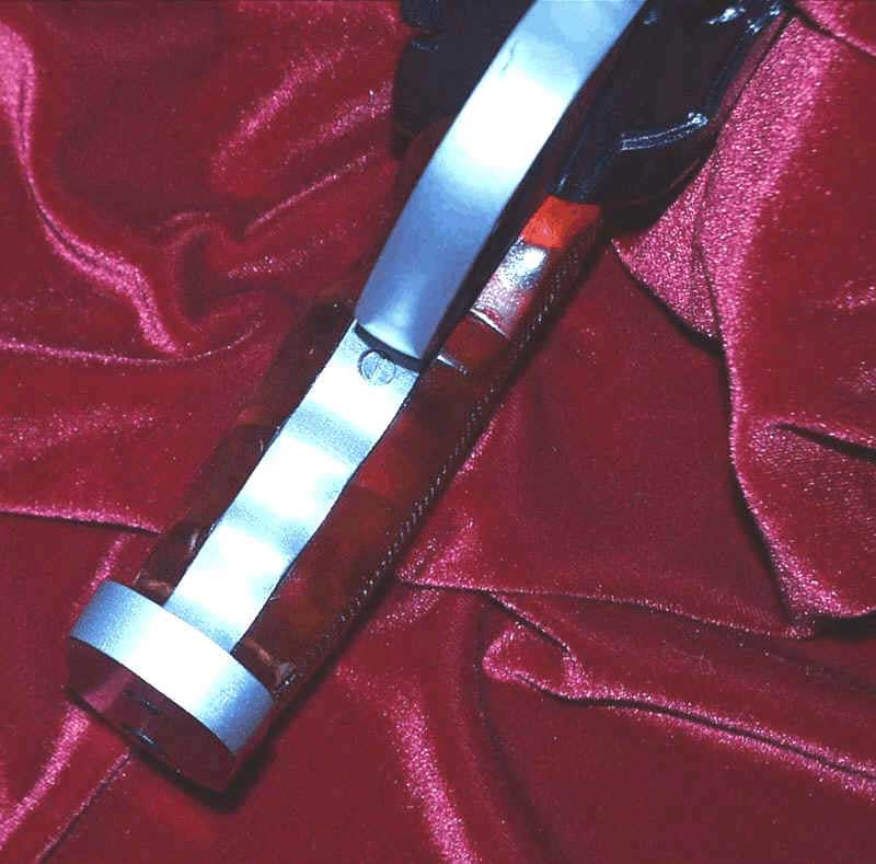 Its
funny. You can watch a movie frame by frame a thousand times scrutinizing every
detail and still miss something obvious. I dont know how many times I
have analyzed the Deckards-hand-through-the-wall sequence and never noticed
it. Craig called me up one night saying he had been doing the frame-by-frame
thing again and noticed something he had never seen before a shadow that
looked a lot like a screw in the front of the pistol grip handle under the trigger
guard. Incredulous, I launched my laser disc and grabbed one of my stunt copies
as he spoke. There it was. I had missed it in the parting line! From the Planet
Hollywood photos and other stunt copies, he had
Its
funny. You can watch a movie frame by frame a thousand times scrutinizing every
detail and still miss something obvious. I dont know how many times I
have analyzed the Deckards-hand-through-the-wall sequence and never noticed
it. Craig called me up one night saying he had been doing the frame-by-frame
thing again and noticed something he had never seen before a shadow that
looked a lot like a screw in the front of the pistol grip handle under the trigger
guard. Incredulous, I launched my laser disc and grabbed one of my stunt copies
as he spoke. There it was. I had missed it in the parting line! From the Planet
Hollywood photos and other stunt copies, he had 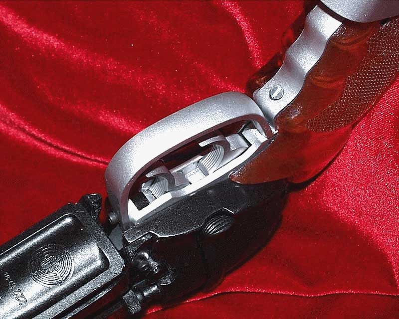 also noticed that I was using an Allen head cap screw where another flat head
slotted screw originally went into the back of the pistol frame. His urging
made me take the extra afford to find and use a variety of screws and thus make
all the fastener details as accurate as possible. All nitpicking aside, his
biggest contribution was in spotting the finer detail differences identifiable
in the earliest generation Steyr SL receivers relative to later versions. He
noted that the early model used smaller dot imprints for the onoff safety
indicators, and that the letter spacing was ever so slightly tighter on the
early Steyrs. Although the character font seems identical, the shape of the
letter "S" was decidedly different, too. Once he pointed it out these
subtle differences, I also noticed that the name stamping was also weaker on
the early runs, especially at the beginning of the word MANNLICHER, where the
letters M-A-N-N were not struck as deeply as were all the other letters
perhaps a flaw in the original die. The chamfer on the ejector port was a touch
different as well. Details, details
also noticed that I was using an Allen head cap screw where another flat head
slotted screw originally went into the back of the pistol frame. His urging
made me take the extra afford to find and use a variety of screws and thus make
all the fastener details as accurate as possible. All nitpicking aside, his
biggest contribution was in spotting the finer detail differences identifiable
in the earliest generation Steyr SL receivers relative to later versions. He
noted that the early model used smaller dot imprints for the onoff safety
indicators, and that the letter spacing was ever so slightly tighter on the
early Steyrs. Although the character font seems identical, the shape of the
letter "S" was decidedly different, too. Once he pointed it out these
subtle differences, I also noticed that the name stamping was also weaker on
the early runs, especially at the beginning of the word MANNLICHER, where the
letters M-A-N-N were not struck as deeply as were all the other letters
perhaps a flaw in the original die. The chamfer on the ejector port was a touch
different as well. Details, details
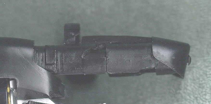
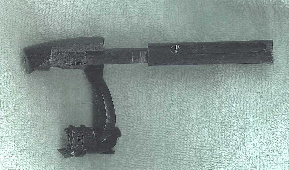
Well, my response to Craig was, "Either loan us the right receiver so I can correct these so-minor-whos gonna-ever-know details by spending a zillion hours making new molds and masters for purity sake, or shut up!" He said "Sure!" to loaning out the right receiver and only asked that I return cast copies along with his original to help guide him with plastic test runs for his project to machine the real Steyr receiver.
 Craig
further challenged me to save the locking lugs. I told him there was NO WAY
that the mold rubber would become caught and that there would be no way
to support the inner mold and
in the middle of going on about how it could
not be done, a light bulb went off and I saw a possibility! So I agreed to give
it a try, and sure enough, it worked! I cast his receiver with the locking lugs
intact and then cast the cocking lever with its locking lugs intact. Eureka!!
Bolt action perfection.
Craig
further challenged me to save the locking lugs. I told him there was NO WAY
that the mold rubber would become caught and that there would be no way
to support the inner mold and
in the middle of going on about how it could
not be done, a light bulb went off and I saw a possibility! So I agreed to give
it a try, and sure enough, it worked! I cast his receiver with the locking lugs
intact and then cast the cocking lever with its locking lugs intact. Eureka!!
Bolt action perfection.
Now I could kill two birds with one stone: I could make the cocking lever even more accurate and actually lock into the receiver, while at the same time I could simplify all that time spent to machine a metal sleeve to mount the cocking arm. So I re-machined the new receiver castings; re-worked the bolt and fitted the new casting of the lugged cocking lever to it; and machined the new bolt and lever assembly to clear the Bulldog frame. Finally, I re-worked the end cap to help eliminate a weakness of the first model and to help hold the cocking lever onto the bolt.
Blade Runner Blaster: Take Two
By Richard A. Coyle
Not long after I completed the first run of working Blasters and penned the Making of saga, Craig Kovach was writing and talking with me about the really finer and nitpicking details of both my model and the real Blade Runner Blaster. Craig had been doing some of his own homework, and after a tip from Phil Steinschneider, he visited a nearby Planet Hollywood that had one of the stunt props in a display case. He took as many pictures as possible to share and, aided with a very poor sixth generation casting of one of the stunt castings and his own well-worn copy of Blade Runner The Directors Cut on DVD, kept grilling me relentlessly on details.
Its funny. You can watch a movie frame by
frame a thousand times scrutinizing every detail and still miss something obvious. I
dont know how many times I have analyzed the Deckards-hand-through-the-wall
sequence and never noticed it. Craig called me up one night saying he had been doing the
frame-by-frame thing again and noticed something he had never seen before a shadow
that looked a lot like a screw in the front of the pistol grip handle under the trigger
guard. Incredulous, I launched my laser disc and grabbed one of my stunt copies as he
spoke. There it was. I had missed it in the parting line! From the Planet Hollywood photos
and other stunt copies, he had also noticed that I was using an Allen head cap
screw where another flat head slotted screw originally went into the back of the pistol
frame. His urging made me take the extra afford to find and use a variety of screws and
thus make all the fastener details as accurate as possible. All nitpicking aside, his
biggest contribution was in spotting the finer detail differences identifiable in the
earliest generation Steyr SL receivers relative to later versions. He noted that the early
model used smaller dot imprints for the onoff safety indicators, and that the letter
spacing was ever so slightly tighter on the early Steyrs. Although the character font
seems identical, the shape of the letter "S" was decidedly different, too. Once
he pointed it out these subtle differences, I also noticed that the name stamping was also
weaker on the early runs, especially at the beginning of the word MANNLICHER, where the
letters M-A-N-N were not struck as deeply as were all the other letters perhaps a
flaw in the original die. The chamfer on the ejector port was a touch different as well.
Details, details
Well, my response to Craig was, "Either loan us the right receiver so I can correct these so-minor-whos gonna-ever-know details by spending a zillion hours making new molds and masters for purity sake, or shut up!" He said "Sure!" to loaning out the right receiver and only asked that I return cast copies along with his original to help guide him with plastic test runs for his project to machine the real Steyr receiver.
Craig further
challenged me to save the locking lugs. I told him there was NO WAY that the mold
rubber would become caught and that there would be no way to support the inner mold
and
in the middle of going on about how it could not be done, a light bulb went off
and I saw a possibility! So I agreed to give it a try, and sure enough, it worked! I cast
his receiver with the locking lugs intact and then cast the cocking lever with its locking
lugs intact. Eureka!! Bolt action perfection.
Now I could kill two birds with one stone: I could make the cocking lever even more accurate and actually lock into the receiver, while at the same time I could simplify all that time spent to machine a metal sleeve to mount the cocking arm. So I re-machined the new receiver castings; re-worked the bolt and fitted the new casting of the lugged cocking lever to it; and machined the new bolt and lever assembly to clear the Bulldog frame. Finally, I re-worked the end cap to help eliminate a weakness of the first model and to help hold the cocking lever onto the bolt.
Blade Runner Take Two
Once completed, I made new molds and found that the new parts
fit together perfectly â just like they were made for each other,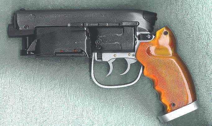 which now, of course, they were!
Craig also kept pestering me about the placement and fit of the grips. And I had to agree they were off a little. First I found that I had placed the angle of the grip frame a bit too far forward. I also heard from a couple of fellow propmakers in LA that owned stunt castings of the prop, who also pointed out that the grips looked too narrow.
Taking another hard look at a good stunt copy I had to work from, I found their observations to be correct. So I powered up my trusty old band saw and commenced to whack away the grips from one of the copies of the stunt castings.
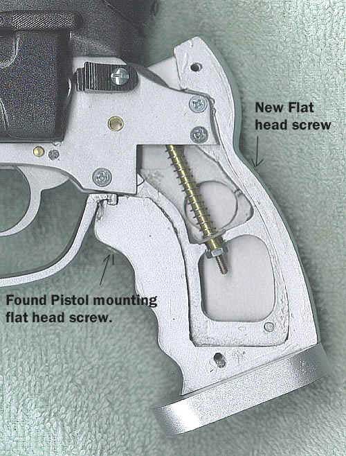
After yet another discussion with Craig about the use of the two flat head screw in the grip frame, I reaffirmed my longstanding belief that they were used to help hold the Bulldog grip frame inside the new oversized frame that they (the original Propmakers on the film) had fabricated for this prop.
 Well,
I concluded that we needed to modify the Blaster pistol grip frame again, so
I decided to follow
Well,
I concluded that we needed to modify the Blaster pistol grip frame again, so
I decided to follow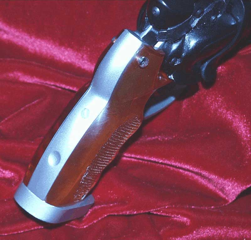 as closely as I could our best guess as to how they (you know who) had done
it. Taking a casting of the Bulldog grip frame, I cut apart one of my first
run Blaster grip frames, lined it up to the Bulldog piece, and mated the two
frames. I even used two 4/40 flat head screws to mount the new "surround"
frame to the smaller Bulldog frame. A little trimming and final fitting to both
of the larger stunt prop pistol grips followed by a final check with the Bulldog-Steyr
frame and receiver and a couple of rounds of sanding and painting to clear up
some minor surface defects, and I proceeded to pop the grip frame into mold
boxes and pour a set of new molds. Out came the second generation of the grip
frame assembly for the Blade Runner Blaster.
as closely as I could our best guess as to how they (you know who) had done
it. Taking a casting of the Bulldog grip frame, I cut apart one of my first
run Blaster grip frames, lined it up to the Bulldog piece, and mated the two
frames. I even used two 4/40 flat head screws to mount the new "surround"
frame to the smaller Bulldog frame. A little trimming and final fitting to both
of the larger stunt prop pistol grips followed by a final check with the Bulldog-Steyr
frame and receiver and a couple of rounds of sanding and painting to clear up
some minor surface defects, and I proceeded to pop the grip frame into mold
boxes and pour a set of new molds. Out came the second generation of the grip
frame assembly for the Blade Runner Blaster.
Hitting a Gun Show on the weekend, I at last found something to better reproduce the diamond crosshatch pattern on the Blaster grips: an Air Soft toy gun model with nearly flat large grips, the same pattern, and no screw holes. As cast rubber, the original stunt prop did not received a very a good impression of the original raised diamond pattern. Air bubbles had been trapped in the diamond recesses causing relatively poor detail reproduction. This was the last flaw that needed to be fixed on our model.
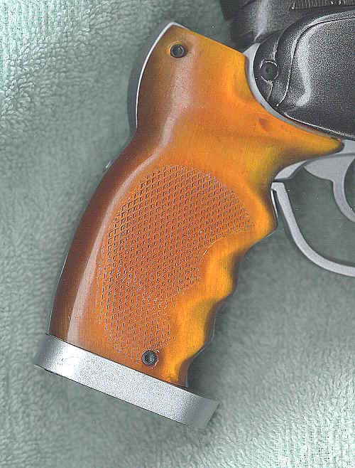 First,
I made a cutout of the correct pattern shape by sanding and trimming a pair
of the stunt grips to within just a hair of the old bubbled diamond pattern.
Then I cut and trimmed the new Air Soft grips to match this outline shape.
First,
I made a cutout of the correct pattern shape by sanding and trimming a pair
of the stunt grips to within just a hair of the old bubbled diamond pattern.
Then I cut and trimmed the new Air Soft grips to match this outline shape.
I cast a mold over them so that I could make a few expendables
to try, just in case I should need extras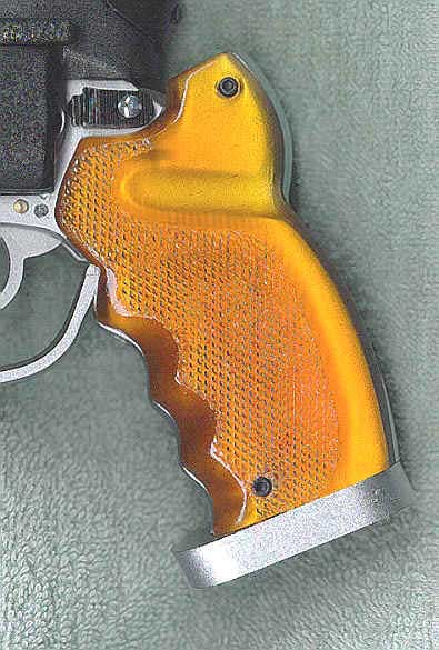 in working out the best way to fit them into the stunt grips to replace the
bad patterns. It was a good thing, too, for it took about three tries to fit
them well. I wound up gluing blocks to the backs of a pair of cast grips, covering
their faces with Vaseline, then placing them face down into a set of old grip
molds with the bad patterns. By placing a Plexiglas plate on top of the blocks
and a heavy vise on top of the plate, I was able to press the diamond patterns
deep into the molds right over the bad patterns. I poured fresh plastic in over
the new patterns pressed into the old patterns, thus molding them right in.
in working out the best way to fit them into the stunt grips to replace the
bad patterns. It was a good thing, too, for it took about three tries to fit
them well. I wound up gluing blocks to the backs of a pair of cast grips, covering
their faces with Vaseline, then placing them face down into a set of old grip
molds with the bad patterns. By placing a Plexiglas plate on top of the blocks
and a heavy vise on top of the plate, I was able to press the diamond patterns
deep into the molds right over the bad patterns. I poured fresh plastic in over
the new patterns pressed into the old patterns, thus molding them right in.
This technique worked perfectly, and with a little sanding and trimming, some filling and painting, and a new set of molds cast over the new clean grips, the last small flaw was gone.
Sometimes all you need is gentle but persistent persuasion from a true fan.